
Build a BrewPi with the One-Size-Fits-Most PCB
Build a modular fermentation controller using the 'One Size Fits Most' PCB with a separate relay board and power supply. The most flexible build — each component is individually replaceable.
What is BrewPi?
What is BrewPi?
BrewPi is an open-source fermentation temperature controller that gives you professional-level control over your brewing process. Originally designed around an Arduino, the modern BrewPi-ESP project uses an ESP32 microcontroller to manage heating and cooling elements connected to your fermentation chamber. Depending on how you choose to build it, a BrewPi-ESP can be assembled entirely from off-the-shelf components with no soldering required — or built with a custom PCB for a more permanent, polished setup. Either way, BrewPi allows brewers to achieve extremely precise temperature control — typically within several tenths of a degree.
Why Temperature Control Matters
Consistent fermentation temperature is one of the most important factors in producing great beer. Even small fluctuations can produce off-flavors, stalled fermentations, or inconsistent results batch to batch. BrewPi solves this by continuously monitoring your wort temperature and adjusting heating/cooling to follow a precise temperature profile.
How It Works
The BrewPi-ESP system consists of three main components:
- Temperature sensors that monitor your wort and chamber temperatures — either wired DS18B20 probes or wireless Bluetooth sensors like Inkbird thermometers or Tilt Hydrometers
- An ESP32 microcontroller that runs the control algorithm and communicates over WiFi
- Switches to control heating and cooling — either physical relays wired to your devices or compatible WiFi smart plugs like TP-Link Kasa
The controller reads sensor data, compares it to your target profile, and activates heating or cooling as needed. You can set simple static temperatures or complex multi-day profiles that ramp up or down over time — perfect for lager fermentation schedules.
What You'll Need
Parts Needed
| Part | Qty |
|---|---|
| 'One Size Fits Most' PCB (preassembled) | ×1 |
| LoLin D32 Pro ESP32 board | ×1 |
| 2-channel 5V relay board | ×1 |
| 5V 2A power supply module | ×1 |
| RJ-45 sensor breakout board | ×1 |
| DS18B20 waterproof temperature sensor (1m or 2m) | ×2 |
| Ethernet cable (straight-through) | ×1 |
| Female-to-female dupont cables | ×6-10 |
| LoLin TFT 2.4" touch screen (optional) | ×1 |
| LoLin TFT cable (required if using LoLin screen) | ×1 |
| Enclosure/project box | ×1 |
| AC power cord (or power inlet) | ×1 |
| AC outlet (for heating/cooling outputs) | ×1 |
What You'll Need
The "One Size Fits Most" PCB is a modular design — the controller board, relay board, and power supply are all separate components connected with dupont jumper cables inside an enclosure. This means more internal wiring than the All-in-One build, but each component can be individually replaced if something fails.
The PCB
The easiest route is to buy the pre-assembled PCB from Tindie. The Tindie version comes with all SMD components and most through-hole components pre-soldered — you'll just need to solder the pin headers, screw terminal, and box header.
If you want to build from scratch, design files are available on GitHub. The full BOM costs around $15–20.
The Controller
The LoLin D32 Pro plugs directly into the two 16-pin female headers on the PCB. The D32 Pro is required if you want to use the LoLin TFT screen.
Relay Board
A standard 2-channel 5V relay board — the kind commonly available on Amazon or AliExpress. This connects to the PCB using dupont cables. The relay board controls your heating and cooling devices by switching mains power.
Tip: Save the jumper that comes with the relay board (the one connecting VCC and JD-VCC). You'll use it for the OneWire voltage selector on the main PCB.
Power Supply
A 5V 2A power supply module provides DC power to the relay board and controller. This is a separate module wired inside your enclosure.
Temperature Sensors
Like the All-in-One build, this board uses wired DS18B20 temperature sensors connected to a separate RJ-45 sensor breakout board via an ethernet cable. You'll want at least two DS18B20 probes (beer and fridge), with an optional third for room temperature.
Display (Optional)
This board supports three display options (use only one at a time):
| Display | Connection | Notes |
|---|---|---|
| LoLin TFT 2.4" | Ribbon cable to D32 Pro | Color touchscreen, easiest option |
| ILI9341 TFT | 10-pin box header on PCB | Generic color TFT alternative |
| LCD2004 | 4-pin IIC header on PCB | Classic monochrome display — requires SMD components to be soldered on the PCB |
Enclosure
This build involves mains voltage and must be enclosed in a project box. The enclosure needs to be large enough to house the main PCB, relay board, and power supply as separate pieces. 3D-printable case designs are available in the hardware GitHub repo.
Wire, Connectors, Outlet, Inlet/Cord
You will need appropriately sized wire for the loads that your device may carry. Typically, this means 14 AWG or larger. Using undersized wire is dangerous and can lead to a fire.
You will additionally need some way to connect the wires together - either wire nuts or wago connectors.
To get power into your project you will either need a stripped AC power cord (and strain relief) or the appropriate power inlet. I recommend IEC320 C14 power inlets, as the matching cables are readily available and come in appropriate gauges for most loads.
You will also need a way to connect your heating/cooling source to the relay PCB. I typically recommend using a standard duplex outlet as they are cheap, and the "fin" connecting the two receptacles can be broken allowing separate control of the top and bottom, enabling a single duplex outlet to be used to control both heating and cooling loads.
Tools
- Soldering iron and solder
- Wire strippers
- Small Phillips screwdriver (for screw terminals)
- A computer with a USB port and web browser (for firmware flashing)
- Appropriate USB cable (for flashing firmware to the D32 Pro)
Assemble the PCB
Assemble the PCB
If you bought the pre-assembled PCB from Tindie, the SMD components (resistors, capacitors, MOSFETs) are already soldered. You just need to add the RJ-45 Jack, male (pin) and female dupont connectors, screw terminal, and (optional) box header.
Solder the Required Through-Hole Components
If using the Tindie board, solder the following components to their labeled positions:
- 16-pin female headers (x2) — these are the sockets for the D32/D32 Pro controller
- 4-pin male headers (x2) — one (required) for the "RELAY" connection, one (optional) for the "LCD" IIC connection
- 3-pin male header (x1) — the ONEWIRE_VSEL voltage selector
- 2-pin male header (x1) — the "PWR" connection for the relay board
- 10-pin box header (x1) — (optional) for non-Lolin TFT display connection
- 2-terminal screw clamp (x1) — power input
Male pin headers typically come in 40-pin strips — snap them to the required lengths (4, 4, 3, and 2 pins). The box header has a "notch" which needs to point towards the white box on the silkscreen.
Note about Displays
The reason this board is called the "one size fits most" PCB is because it supports three different display types:
- LoLin 2.4" TFT connected directly to a D32 Pro using their cable
- Third party ILI9341-based 320x240 TFT connected via the box header
- LCD2004 monochrome display connected to the "LCD" header
When using the LCD2004 monochrome display, the SMD components are required to be attached to the PCB, as these serve as a level shifter to achive the voltage that display requires. These components - Q1, Q2, R3, R4, R5, R6 - are not optional, and the LCD2004 will not work if they are missing.
When using a third party ILI9341-based TFT, the box header breaks out the 10 pins required for the display to function. This is intended to be used with a "LCD Breakout PCB" which I have designed, which can be soldered onto the pins of the TFT.
When using the LoLin 2.4" TFT all of the connectors/components required come pre-attached to the D32 Pro. Neither the box header or the SMD level shifter are required.
Building from Scratch
If you ordered a bare PCB, you have the option of using SMD or through-hole components for the required capacitors and resistors to make the device work. If you plan to use an LCD2004 display, however, the level shifter is only implemented when using SMD components.
Once you have attached the resistors/capacitors/MOSFETs listed below, you will need to attach the through-hole components listed above, including the RJ-45 modular jack.
Using Through-hole Components
If you use the through-hole components, you must not attach SMD components at R1, or C1, C2, C5, and C6. These SMD components are replaced by the through-hole equivalents listed below.
- Resistor: One 4.7kΩ resistor at R2
- 0.1µF Capacitors: Attach two 0.1µF capacitors at C3 and C7
- 1.0µF Capacitors: Attach two 1.0µF capacitors at C4 and C8
Again - if you ordered a PCB that has SMD components already attached, you do not need to attach the components listed above.
Using SMD Components
If you prefer to use SMD components (or plan to use an LCD2004 display) attach the following:
- Resistors: four 10kΩ 0805 at R3, R4, R5, and R6 and one 4.7kΩ 0805 at R1
- Capacitors: two 0.1µF 0805 and C1 and C5 two 1.0µF 0805 at C2 and C6
- MOSFETs: two BSS138 MOSFETs at Q1 and Q2
Note: The SMD components (resistors, capacitors, MOSFETs) are only required if you want to use an LCD2004 display over IIC. If you're only using the LoLin TFT or an ILI9341 TFT, you can skip the SMD components entirely and build a through-hole-only board.
Prepare the Controller
If your LoLin D32/D32 Pro does not already have 2 rows of 16-pin male headers attached, attach them now, pointing down (away from the metal shielding covering the ESP32).
Install the Controller
Plug the LoLin D32/D32 Pro into the two 16-pin female headers. Make sure the USB port faces the same direction as the RJ-45 jack on the PCB.
Set the OneWire Voltage
The ONEWIRE_VSEL 3-pin header controls the voltage supplied to DS18B20 temperature sensors. Place the jumper (the one you saved from the relay board, or any 2.54mm jumper) to connect the "OW" pin to either:
- 5V — start here, works with most sensors
- 3V3 — try this if your sensors don't respond at 5V
If you do not have a movable jumper - or would prefer to permanently set the voltage - you can create a solder bridge between the desired voltage and the "SEL" pad using the provided solderable jumper pads. Do not bridge all three pins/pads or you will destroy the controller (and may destroy other components).
Connect the TFT Screen (Optional)
- LoLin TFT: Connect directly to the D32 Pro via the LoLin TFT ribbon cable — no connection to the PCB needed
- ILI9341 TFT: Connect the appropriate ribbon cable between the 10-pin box header on the PCB and the 10-pin box header on the LCD's "backpack"
- LCD2004: Connect to the 4-pin "LCD" IIC header (requires SMD components soldered)
NOTE - Only one display can be used at a time.
Connect the Temperature Sensors
Parts Needed
| Part | Qty |
|---|---|
| DS18B20 waterproof temperature sensor | ×2 |
| RJ-45 sensor breakout board | ×1 |
| Ethernet cable | ×1 |
Connect the Temperature Sensors
Like the All-in-One build, the "One Size" PCB uses an RJ-45 sensor breakout board for temperature sensors. DS18B20 probes are soldered to the sensor breakout board, which then connects to the main PCB via a standard ethernet cable.
Prepare the Sensor Breakout Board
If you bought the sensor board from Tindie, the RJ-45 jack and screw terminal are already soldered. If you have a bare board, solder those on first.
Test Your Sensors First
Before permanently soldering the DS18B20 sensors, if you can, temporarily hold the sensor wires against the pads to verify they work. Once confirmed, solder them in place.
Solder the DS18B20 Sensors
Each DS18B20 waterproof probe should have three wires. Solder them to the labeled pads on the sensor breakout board:
| Typical Wire Color | Function |
|---|---|
| Red | VCC (power) |
| Black | GND (ground) |
| Yellow or White | Data |
Although these colors are typical, they are not standardized. If your sensors come with documentation that indicates different colors, use those instead.
The board supports up to three sensors:
- Sensor 1 — Fridge/chamber temperature (place inside chamber, away from heating/cooling elements)
- Sensor 2 — Beer temperature (attach probe to fermenter, insulated with foam)
- Sensor 3 (optional) — Room temperature
All sensors share the same OneWire data line, and each has a unique address — the firmware identifies them automatically.
Note: The sensors must be wired in standard 3-wire mode. Do not use parasitic (2-wire) mode — it is not supported.
Connect to the Main PCB
Plug a standard straight-through ethernet cable from the sensor breakout board's RJ-45 jack into the RJ-45 jack on the main PCB. Power and data for the sensors both run through the ethernet cable.
Sensor Placement Tips
- Beer sensor: Tape or strap the probe to the side of your fermenter, about one-third up from the bottom. Cover it with foam or bubble wrap so it reads the beer temperature rather than the chamber air.
- Fridge sensor: Place inside the chamber but away from the fermenter walls and away from direct airflow from heating or cooling elements.
- Room sensor (optional): Place outside the fermentation chamber in the same room.
Connect the Relay Board and Power Supply
Connect the Relay Board and Power Supply
The "One Size" PCB uses a separate relay board and power supply module, connected with dupont jumper cables. This is the step with the most internal wiring, so take your time and double-check connections.
Parts Needed
- 14 AWG or larger wire
- Wire nuts
Prepare the Relay Board
Before connecting, remove the jumper that bridges the VCC and JD-VCC pins on the relay board. Set this jumper aside — you'll use it for the OneWire voltage selector on the main PCB (if you haven't already).
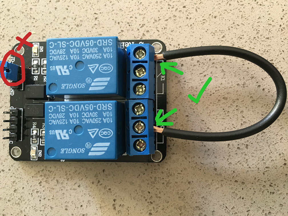
Additionally, cut a small piece of wire and attach to the center screw terminal of one relay, and connect it to the right hand screw terminal of the other. This piece of wire will simplify the wiring later, and also ensure that we can only power one device (heat or cool) at a time.
Connect the Relay Signal Cables
Using four female-to-female dupont cables, connect the 4-pin "RELAY" header on the main PCB to the relay board's input header. The pin order should match — but double check the pin labeling between the "One Size" PCB and the relay board itself:
| PCB "Relay" Pin | Relay Board Pin |
|---|---|
| GROUND | GND |
| COOL | IN1 |
| HEAT | IN2 |
| 3V3 | VCC |
Connect the Relay Power
Using two female-to-female dupont cables, connect the 2-pin "PWR" header next to the on the main PCB to the relay board:
| PCB "PWR" Pin | Relay Board Pin |
|---|---|
| 5V | JD-VCC |
| GND | GND |
JD-VCC may be labeled "RY-VCC" (or have another label) depending on your relay board. The important bit is that you never connect +5V to the bare "VCC" pin.
This provides isolated 5V power to the relay coils.
Connect the Power Supply
Wire the 5V 2A power supply module to the main PCB's 2-terminal screw clamp, connecting GND on the power supply to GND on on the "5V_IN" connector, and +5V from the power supply to 5V on the "5V_IN" connector. The power supply converts mains AC to 5V DC, powering both the ESP32 controller and the relay board.
Wire Mains Power
⚠️ Safety Warning: This step involves mains voltage. Work with everything unplugged and double-check all connections before applying power.
The mains wiring is similar to the All-in-One build:
- Wire your AC power cord to the power supply module's AC input terminals
- Wire the relay board's switched outputs to your heating and cooling devices — one relay for heating, one for cooling
The specifics depend on your relay board and power supply module. In general:
- The power supply needs mains AC in and provides 5V DC out (to the PCB screw terminal)
- Each relay switches the hot wire going to one of your devices (heating or cooling)
- The neutral wire passes straight through to the devices
Enclosure Layout
Arrange the components inside your project box:
- Main PCB — mount securely with standoffs or screws
- Relay board — mount nearby with dupont cables reaching comfortably
- Power supply module — mount with appropriate clearance for mains wiring
Route the dupont cables neatly and ensure all mains wiring is securely terminated. Do not operate outside of an enclosure.
Power On
Plug in the AC power cord. You should see:
- The power supply provides 5V to the PCB
- The D32 Pro boots up (the screen shows the boot sequence if connected)
- The relay board's power indicator LED lights up
Flash the Firmware with BrewFlasher
Flash the Firmware with BrewFlasher
BrewFlasher is a free tool that downloads and flashes the correct firmware to your ESP32 or ESP8266 automatically — no command line needed. It supports all of the major brewing-related ESP projects including BrewPi-ESP, TiltBridge, and more.
You have three options for flashing: the desktop app (Windows/macOS), the web edition (Desktop Chrome/Edge only), or the command line edition (most OSes, including Raspbian/Raspberry Pi OS).
Option A: BrewFlasher Desktop App
- Download the latest release from the BrewFlasher GitHub releases page
- Connect your ESP32 to your computer with a USB cable
- Open the app — no installation required, just double-click
- Select the appropriate serial port (or choose Auto-select)
- Select the appropriate project, device family, and firmware you want to flash
- Click Flash and wait for it to complete
Note - When flashing some devices for the first time, you may need to hold down a button (typically labeled "boot" or "0") when connecting to the computer. You can release the button a few seconds after the device is plugged in.
Option B: BrewFlasher Web Edition
- Open web.brewflasher.com in Google Chrome, Microsoft Edge, or Opera on a computer (other browsers including Safari and Firefox don't support WebSerial)
- Connect your ESP32 to your computer with a USB cable
- Select the project, device family, and firmware you want to flash
- Click "Flash to Controller"
- You will be prompted by your browser to connect a device - select the controller you connected (typically "USB Serial" or similar)
- Click "Install" and wait for the flash to complete
Option C: BrewFlasher Command Line Edition
The command line edition works on any platform with Python — including Raspberry Pi / Raspbian — and provides the same interactive firmware selection as the desktop app.
- Install via pip (if not already installed):
pip install --upgrade brewflasher_cli - Connect your ESP32 to your computer with a USB cable
- Run
brewflasher— it will interactively walk you through selecting a project, device family, firmware, and serial port - Wait for the flash to complete
You can also skip the interactive prompts by passing options directly:
brewflasher --serial-port /dev/ttyUSB0 --baud 460800
Run brewflasher --help for a full list of options.
Troubleshooting
- Device not detected? Try a different USB cable — some cables are charge-only and don't carry data. Also try a different USB port.
- Flash fails on ESP32-S2? Some boards require you to manually enter flash mode: hold the 0 button, press RST, then release 0. Then try flashing again.
- Linux permissions error? Run
sudo usermod -a -G dialout $USER, log out and back in, then try again.
Once the flash completes, your device will reboot and the new firmware will be running.
For this build, select **BrewPi-ESP** as the project in BrewFlasher, and choose the firmware version for the **ESP32**. If you're using a LoLin D32 Pro with the TFT screen, make sure to select the firmware variant that includes TFT support.
Connect to WiFi
Connect to WiFi
After flashing the BrewPi-ESP firmware, the controller needs to be connected to your home WiFi network. On first boot, it creates its own WiFi access point that you'll use to enter your network credentials.
Connect to the Setup Access Point
- Power on the controller (plug in the USB cable)
- On your phone or computer, open your WiFi settings and look for a network called BrewPiAP
- Connect to it using the password brewpiesp
- A configuration page should open automatically. If it doesn't, open a browser and navigate to
http://192.168.4.1
Enter Your WiFi Credentials
- Select your home WiFi network from the list (or type the name manually)
- Enter your WiFi password
- Save the settings
The controller will restart and connect to your home network. The BrewPiAP network will disappear.
Find the Controller on Your Network
Once connected, you need to find the controller's IP address to access its web interface:
- If you have the TFT screen: The IP address is displayed in the lower-left corner of the screen
- If you don't have a screen: Check your router's connected devices list, or use a network scanner app like Fing on your phone to look for the new device
Open a web browser on any device connected to the same WiFi network and navigate to the controller's IP address (e.g., http://192.168.1.100). You should see the BrewPi-ESP web interface.
Tip: Bookmark the IP address or assign a static IP through your router so you can easily find the controller later.
For the One Size build, you can flash the firmware over USB before wiring mains power. Once WiFi is configured and you've verified the web interface loads, proceed to the relay and power wiring step.
Configure Sensors and Relays
Configure Sensors and Relays
With everything wired up and the controller on your WiFi network, the last step is assigning each sensor and relay to its role in the BrewPi-ESP web interface.
Open the Configuration Page
- Navigate to your controller's IP address in a web browser
- Go to the Set Up Sensors/Actuators page
Assign Temperature Sensors
The page will show all detected DS18B20 sensors by their unique addresses. For each sensor, assign its role:
- Beer Sensor — the probe attached to your fermenter
- Fridge Sensor — the probe inside the fermentation chamber
- Room Sensor (optional) — the probe outside the chamber
If you're not sure which address corresponds to which sensor, warm one sensor with your hand and watch the temperature reading change — that tells you which is which.
Assign Relay Outputs
The two relays should appear on the configuration page. Assign each to its role:
- Cool Actuator — the relay connected to your cooling device
- Heat Actuator — the relay connected to your heating device
Test the Relays
Set a target temperature to verify the relays respond:
- Set a target below the current beer/fridge temperature — the cooling relay should activate (you'll hear it click)
- Set a target above the current temperature — the heating relay should activate
If the wrong relay fires, swap the heat and cool assignments in the configuration.
Save and Verify
Save the configuration. The web interface should now show live temperature readings from all connected sensors, and the controller will begin managing temperature automatically based on your setpoint.
Next Steps
Next Steps
Your "One Size Fits Most" BrewPi is assembled, wired, and configured. Here's what to do next.
Connect to a Dashboard
While the BrewPi-ESP's built-in web interface works fine on its own for basic control, you can connect it to a web-based dashboard for richer logging, graphing, and remote access:
- Fermentrack.net — Free, cloud-hosted, modern fermentation management. Tracks temperatures, manages profiles, and logs history across multiple controllers from anywhere in the world.
- Fermentrack — Self-hosted fermentation management on a Raspberry Pi.
- BrewPi Remix — An updated version of the original BrewPi web interface, also self-hosted on a Raspberry Pi.
Connection instructions vary by platform — refer to each project's documentation for setup details.
Tips for Reliable Operation
- Check your enclosure periodically — make sure all dupont cables are firmly seated and mains wiring connections remain tight
- Keep the controller plugged in to a reliable power source — if it loses power, the relays open and your heating/cooling devices turn off
- Assign a static IP to the controller through your router so you always know where to find it
- Protect the sensor cable — the ethernet cable between the main board and the sensor breakout can get snagged or pulled. Route it securely
- Label your dupont cables — if you ever need to open the enclosure for maintenance, labeled cables save time